
Monday, 24 December 2012
LCD based digital alarm clock

Sunday, 23 December 2012
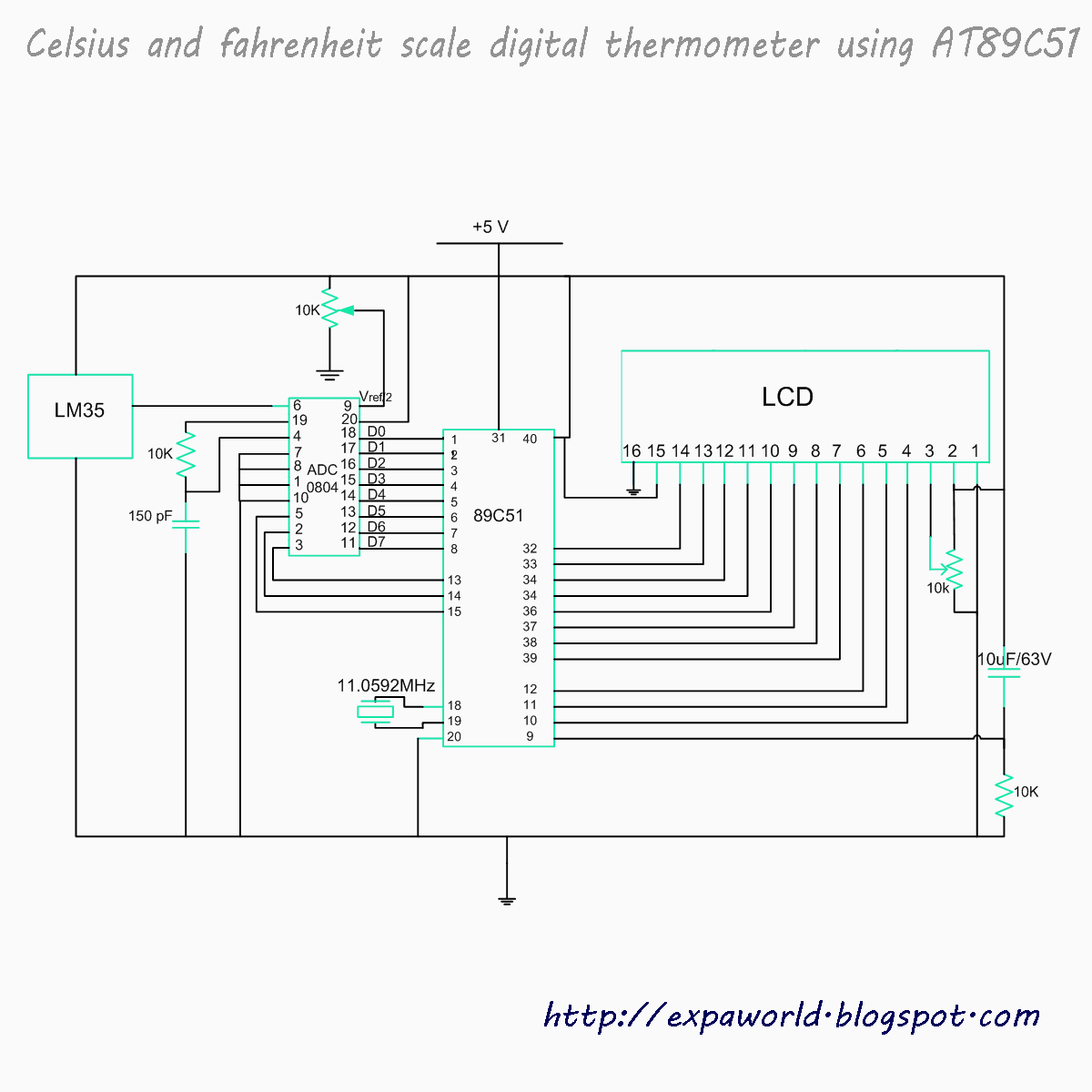
Celsius and fahrenheit scale digital thermometer using AT89C51
Saturday, 22 December 2012
Simple Digital clock using 8051 microcontroller (AT89C51)

Automatic bidirectional visitor counter using 8051 microcontroller (AT89C51)

A counter that can change its state in either direction, under control of an up–down selector input, is known as an up–down counter. The circuit given here can count numbers from 0 to 9999 in up and down modes depending upon the state of the selector. It can be used to count the number of persons entering a hall in the up mode at entrance gate. In the down mode, it can count the number of persons leaving the hall by decrementing the count at exit gate. It can also be used at gates of parking areas and other public places.
This circuit divided in three parts: sensor, controller and counter display. The sensor would observe an interruption and provide an input to the controller which would run the counter in up/down mode depending upon the selector setting. The same count is displayed on a set of 7-segment displays through the controller.
Monday, 26 November 2012

Interface a keypad with Microcontroller

Keypad is organized as a matrix of switches in rows and column. The article uses a 4X3 matrix keypad and a 16x2 LCD for displaying the output of keypad.
The circuit diagram shows the connection of keypad with the controller. Port P2 of the microcontroller is used to send the data for displaying on the LCD. P1^1, P1^2, P1^3 pins of microcontroller is connected to RS, RW, EN pins of LCD respectively. Port P0 is used to scan input from the keypad (refer circuit diagram for connection).
The concept of interfacing keypad with the MCU is simple. Every number is assigned two unique parameters, i.e., row and column number (n(R, C) for example 6 (2, 3)). Hence every time a key is pressed the number is identified by detecting the row and column number of the key pressed.
Initially all the rows are set to zero by the controller and the columns are scanned to check if any key is pressed. In case no key is pressed the output of all the columns will be high.
Saturday, 24 November 2012
Internal block diagram of DACO800

- The DAC0800 is an 8-bit, high speed, current output DAC with a typical settling time (conversion time) of 100 ns.
- It produces complementary current output, which can be converted to voltage by using simple resistor load.
- The DAC0800 require a positive and a negative supply voltage in the range of ± 5V to ±18V.
- It can be directly interfaced with TTL, CMOS, PMOS and other logic families.
- For TTL input, the threshold pin should be tied to ground (VLC = 0V).
- The reference voltage and the digital input will decide the analog output current, which can be converted to a voltage by simply connecting a resistor to output terminal or by using an op-amp I to V converter.
- The DAC0800 is available as a 16-pin IC in DIP
Subscribe to:
Posts (Atom)